SonicSense Anomaly Detection
A $10 dual-sensor motor health monitor on ESP32-S3 that listens for sound and vibration anomalies, from custom PCB to ML pipeline.
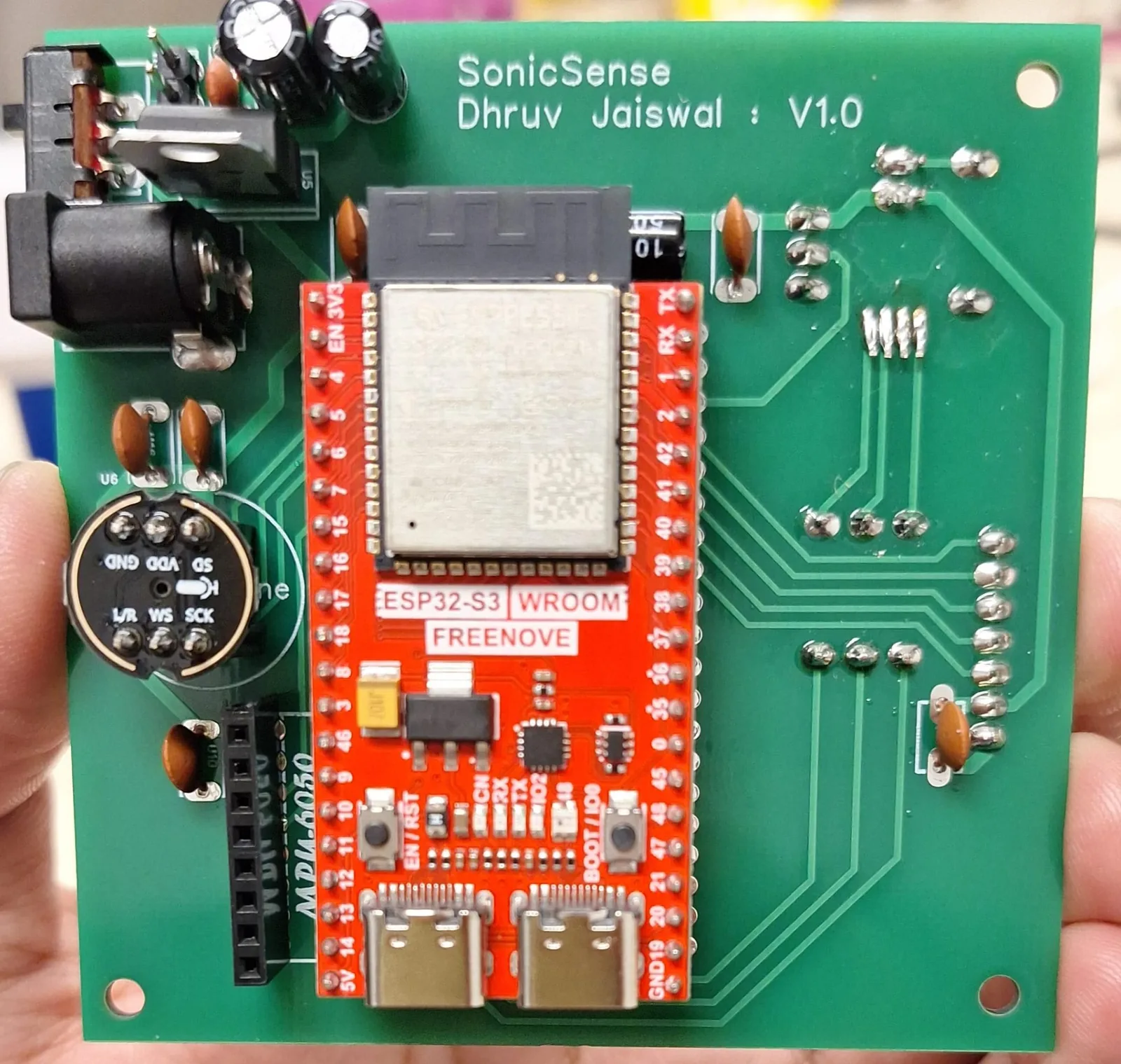
SonicSense V1.0, sensor side
sections
Overview
SonicSense is a low-cost motor health monitor that listens to a machine through two channels at once: a MEMS microphone for airborne sound and an IMU for structure-borne vibration. I built it as the sole engineer on Team 11 in CMU's 49-736 IoT and Smart Systems course, taking it from a breadboard to a fabricated V1.0 PCB, dual-core ESP32-S3 firmware and a Colab training pipeline by the April 29 deadline. The prototype worked as a normal versus anomaly detector. This page also covers the first thing I am changing: replacing the CNN with a much simpler model that learns what healthy sounds like for one specific motor.
Why listen to motors
Our class pitch framed the problem around cost, not awareness. Unplanned downtime costs U.S. manufacturing an estimated $50B a year, and most of it starts with bearings, motors and belts wearing out. Only about 27% of facilities use predictive maintenance, and a typical industrial sensor node costs $500 or more. SonicSense targets roughly $10 of hardware per node: an ESP32-S3, an INMP441 microphone and an MPU6050 IMU. My teammates Gabriella Chen, Jiajun Pan and Zhenzhen Ye covered design and the business case.
Hardware
I validated every sensor on a breadboard before writing any ML code, then moved the design onto a custom PCB. The V1.0 board carries a Freenove ESP32-S3 WROOM module, the INMP441 on I2S, the MPU6050 on I2C, an SSD1306 OLED on SPI, a capacitive touch pad, a tactile button, status LEDs and a barrel-jack power input with an onboard regulator.
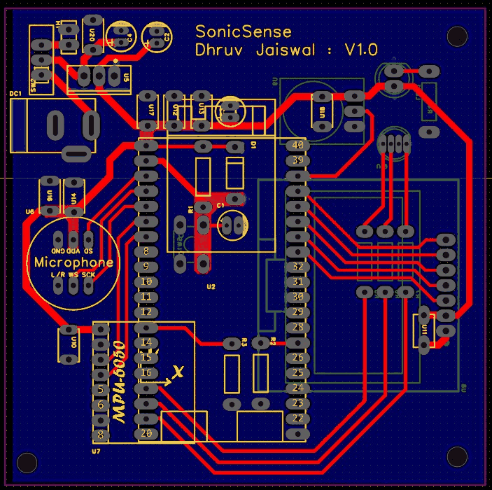
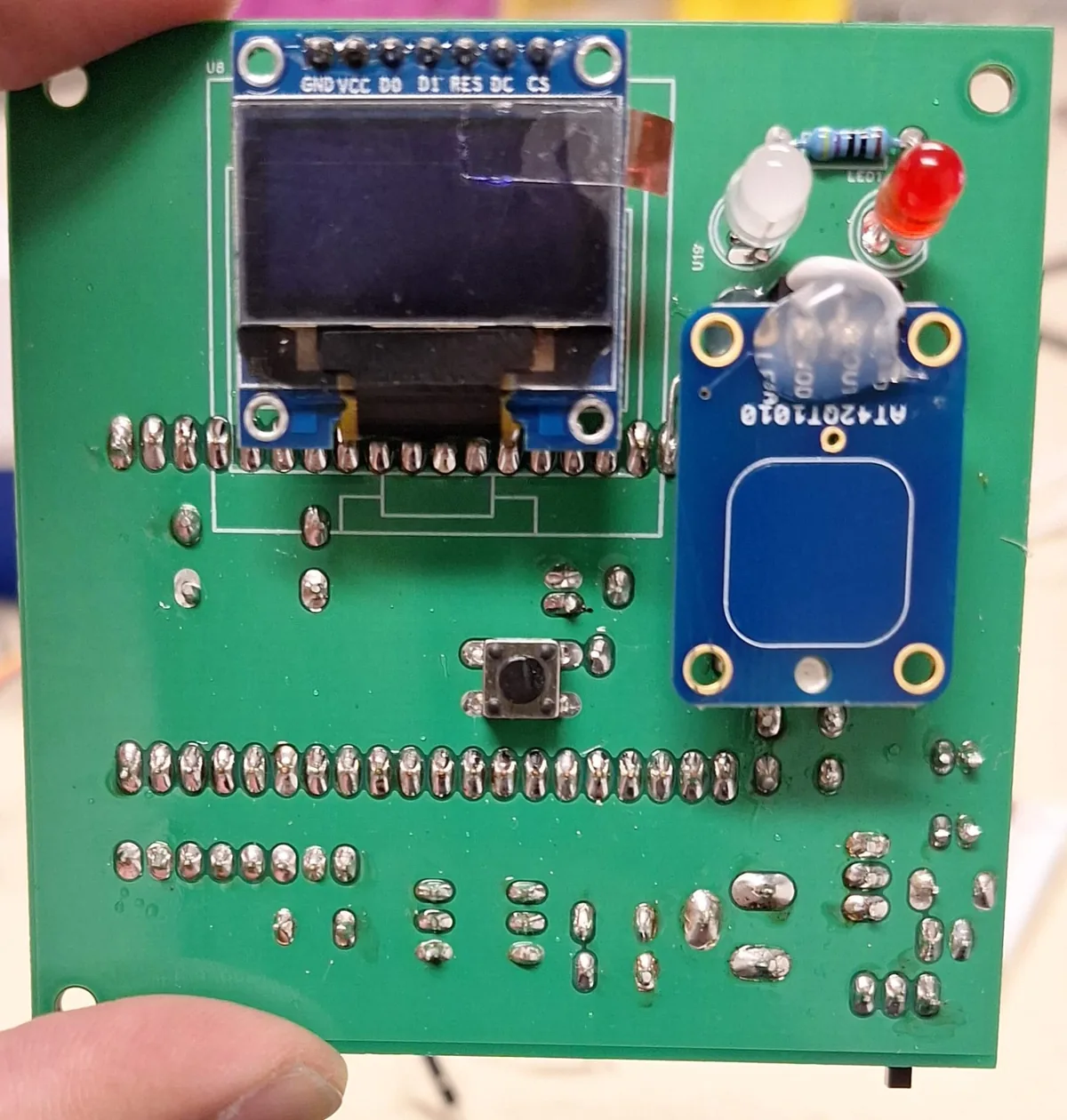
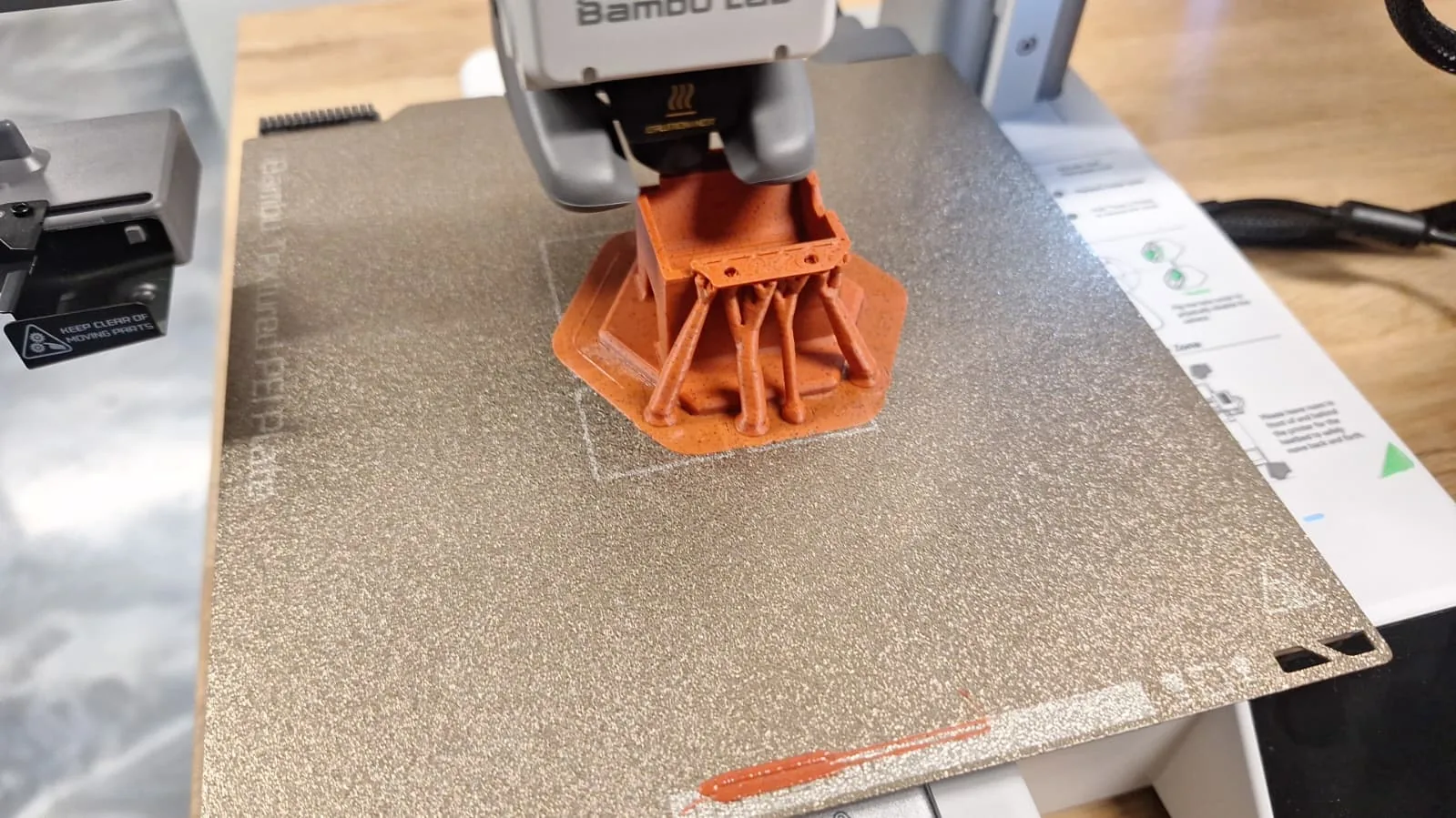
I also 3D printed a rig for the test setup on a Bambu Lab printer.
Firmware
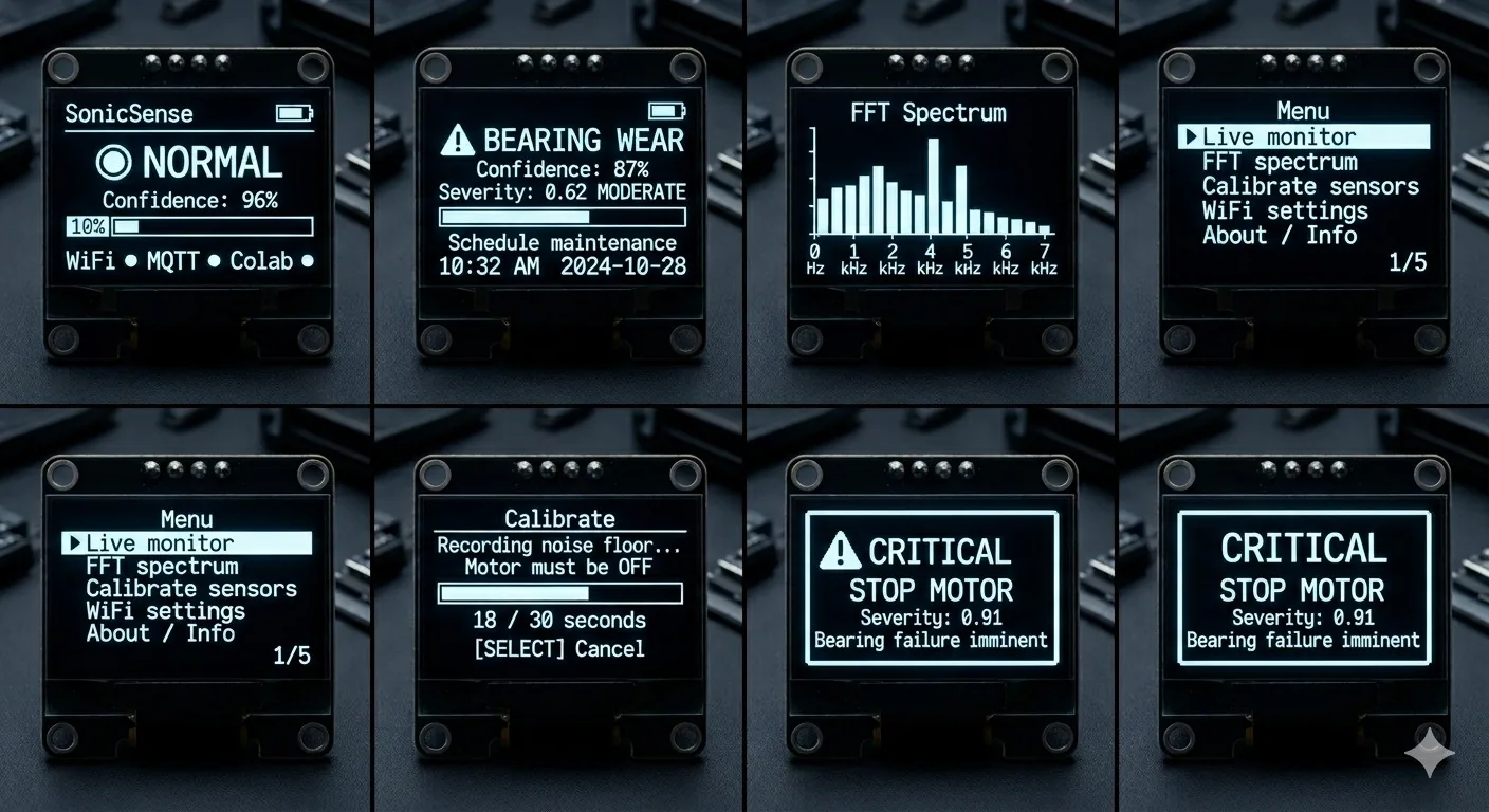
The firmware splits work across the ESP32-S3's two cores. Core 1 runs the DSP pipeline without interruption, while Core 0 handles Wi-Fi, MQTT, the OLED and the touch UI, so a dropped connection never stalls audio capture. On boot the node calibrates against the floor noise of the room, then runs a multi-screen OLED menu and streams features to the serial plotter for debugging. Wi-Fi and MQTT reconnection are non-blocking.
Debugging the microphone that returned garbage
The INMP441 first produced nonsense, and it took three separate fixes to get a clean signal. An int132_t typo had crept into the I2S sketch. The bits-per-sample setting was 16 when the INMP441 delivers 32-bit frames. Once data was flowing, a DC offset swamped the low bands, which I removed with an IIR high-pass filter.
The stack overflow in publishMFCC
publishMFCC() built its JSON payload in a large buffer on the task stack, which tripped the stack canary and rebooted the board. Making the buffer static fixed it. Since then, any large buffer in a task function is either static or on the heap.
Signal processing and the CNN
On the device, each audio frame goes through an FFT, Mel bands and MFCCs. In Colab, a 12-block notebook downloads MaFaulDa, extracts features with librosa in a way that mirrors the ESP32 DSP, trains a CNN with class-weighted loss, scores severity and runs an MQTT inference server. I picked MaFaulDa because it records a fault-simulator motor with both accelerometers and a microphone, the same two modalities SonicSense uses.
The design fuses the sensors at the feature level rather than the raw signal: a Kalman filter weights the accelerometer in the low Mel bands and the microphone in the high ones, after the FFT and before the MFCC step. Integrating that fusion is still in progress.
Tracking down a 43.7× domain gap
When I compared live ESP32 features with the training features, the device MFCCs were 43.7 times off in scale from MaFaulDa. librosa's power_to_db(ref=np.max) scales each clip to its own peak, and the firmware never replicated that step. I recomputed the normalization parameters from MFCCs captured on the ESP32 instead of assuming the training defaults, which put both pipelines on the same scale.
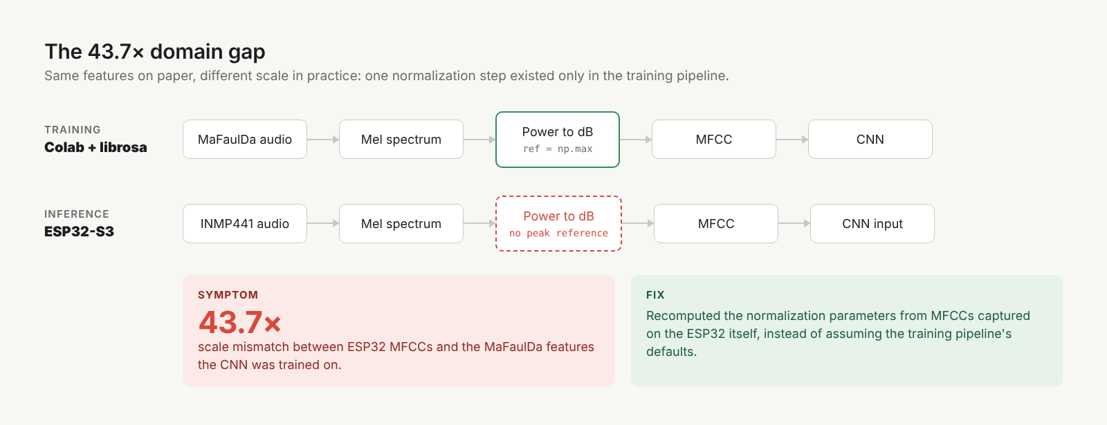
Even with the scale fixed, the lab motor did not sound like MaFaulDa's motor, so its fault classes did not carry over. I collapsed the classifier to normal versus anomaly, which gave a working V1.0 demo.
Rethinking the model
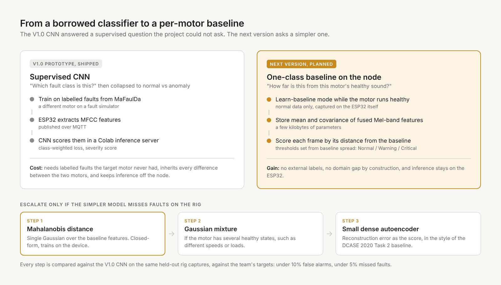
Looking back, the CNN was a naive choice for this stage and more model than the problem needed.
- It answered a question the project could not ask. A classifier needs labelled faults, and the only labelled faults came from a different motor. Once collapsed to binary, it was a one-class problem solved with a two-class model.
- It inherited the domain gap. Every difference between MaFaulDa's motor and ours became error the network could not learn around.
- It ran off the device. Inference lived on the Colab server behind MQTT, which works against the pitch of a node that needs no cloud.
- The signal is simpler than the model. A motor at steady state has a fairly stable spectrum, and the anomaly is the deviation from it.
The machine condition monitoring field frames this as unsupervised anomaly detection: train only on normal sound and score how far new data falls from it. The DCASE 2020 Task 2 baseline, for example, was a small fully connected autoencoder on log-mel features trained only on normal recordings.
The simplest model that could work (Planned)
The first step is a learn-baseline mode next to the existing noise-floor calibration. While the motor runs healthy, the ESP32 accumulates the mean and covariance of the fused Mel-band features. At runtime the anomaly score is the Mahalanobis distance from that baseline, and the Normal, Warning and Critical thresholds come from the spread of scores seen during the baseline. That is a few kilobytes of parameters, needs no external dataset, and removes the domain gap by construction because it trains on the motor it monitors.
If one Gaussian cannot cover several healthy operating states, such as different speeds or loads, the next step is a Gaussian mixture. A small dense autoencoder comes in only if both miss faults on the rig. Each candidate is scored against the V1.0 CNN on the same held-out rig captures, using the targets the team set at the start: under 10% false alarms and under 5% missed faults. Multi-class fault labels come back only once there is enough labelled data from the target motor.
Lessons learned
- Match training data to the inference signal explicitly. Normalization, motor type and sample rate all have to line up, and normalization parameters should come from real device captures.
- Hardware first, software second. Validating the full board before the ML work kept every bug in a small search space.
- Start with the simplest model the problem allows. The CNN cost me time on a domain gap that a per-motor baseline avoids by design.
System architecture
Specifications
- MCU
- ESP32-S3 (Freenove WROOM board)
- Microphone
- INMP441 MEMS, I2S
- Vibration
- MPU6050 6-axis IMU, I2C
- Audio sample rate
- 16 kHz
- Display
- SSD1306 OLED, SPI
- Input
- Capacitive touch pad, tactile button
- Power
- DC barrel jack, onboard regulator
- Firmware
- Core 1 DSP, Core 0 network and UI
- Connectivity
- Wi-Fi, MQTT (Mosquitto)
- Training data
- MaFaulDa